THE TRACK AND WAGONS OF THE SURREY RAILWAYS
CHAPTER 11
Benjamin Outram wrote a description of his recommended method of forming and laying railway tracks, which may "be assumed to be the general procedure employed in constructing the two railways :
"The bed of the road so formed to the proper inclination and the embankments and works thereof made firm, the surface must be covered with a bed of Stones broken small, or good Gravel six inches in thickness or depth, on this bed must be laid the sleepers or blocks to fasten the rails upon. These should be of stone in all places where it can be obtained in Blocks of sufficient size; they should not be less than 8, nor more than 12 inches in thickness; and of such breadths, circular, square or triangular, as shall make them 150 lbs. or 200 lbs. weight each, their shape is not material so that they have a flat bottom to rest upon, and a small portion of their upper surface level to form a firm bed for the end of the rails. In the centre of each block must be drilled a hole one inch and a half in diameter and six inches in depth, to receive an octagonal plug of dry oak five inches in length, for it shall not reach the bottom of the hole, nor should it be larger than so as to be put in easily and without much driving - for if it is too tight fitted it might when wet burst the stone. These plugs are to receive an iron spike or large nail with a flat point and a long head, adapted to fit the countersunk notches in the end of two rails, and thereby fasten them down into proper position.
The rails should be of the stoutest cast iron one yard in length each, formed with a flanch on the inner edge two inches and a half high at the ends and three and a half in the centre, and shaped in the best manner to give strength to the rails for general purposes should not be less than 4 inches broad, and the thickness proportional for the work they are intended for; on railways for heavy burthens, great use, and long duration, the rails should be very stout, weighing 40 lbs., or in some cases nearly half a hundredweight each; for railways of less consequence less weight of metal will do.
In fixing the blocks and rails great attention is required to make them firm, and no earth or soft materials are to be used between the blocks and a bed of small stones or gravel on which they rest. The rails must all be fixed by an iron gauge to keep the sides at a regular distance or parallel to each other. The best width of road for general purposes is 4 feet 2 inches between the flanches of the rails, the wheels of the carriages running in tracks about 4 feet 6 inches as under rails of particular form are necessary where roads branch out from or intersect each other and where carriage roads cross the railway; and at turnings of the road great care is required to make them perfectly easy; the rails on that side forming the inner part of the curve should be /fixed a little lowrer than the other, and the rails should be set a little under the gauge so as to bring the side nearer than in the straight parts; these deviations in level and width to be in proportion to the sharpness of the curve.
The blocks and rails being fixed and spiked fast, nothing remains to be done, but to fill the horse path or space between the blocks, with good gravel, or other proper materials, a little more of which must also be put on the outside of the blocks to keep them in their proper places. This gravelling should always be kept below the surface of the rails on which the wheels are to run, to keep the tracks for the wheels free of dirt and obstructions; the form of the rails must be such as will free themselves from dirt if the gravelling is kept below their level ..."[1]
In practice the composition of the ballast was adapted to suit the soil conditions and locally available materials. The account of the wager made at the opening of the Croydon, Merstham and Godstone Iron Railway quoted in Chapter 5 went on to describe the trackbed as a "composition of white chalk and flints, pounded, watered and rolled, with a small sprinkling of gravel on top." [2]
The stone sleeper blocks on both railways were generally about 15 or 16 inches square and 8 or 9 inches thick, but some smaller ones are known. They were unwrought except for a smoothed length on top on which the rails rested.
The cast-iron rails were typically 3 feet long, basically L-shaped in section, with an approximately 4 inch wide horizontal running plate and a vertical flange about 3 inches high but curved in elevation so that it was higher in the centre. There was a similarly curved but smaller strengthening rib on the other side of the running plate and projecting beneath it. The ends of the plate were thickened where they were supported on the sleeper blocks, and in the outside edges of each of these sections a rectangular notch was formed. An iron spike was driven through the hole formed by the abutment of two adjacent notches, into the oak plug in the sleeper as described by Outram. There were dimensional and other differences in various contemporary descriptions and surviving rails, and it is best to consider the two railways separately in this respect.
Only one, damaged, rail from the Surrey Iron Railway has been found, and this is preserved in the Science Museum, London. This is 3 feet long, the maximum height of the flange above the horizontal plate is 2 inches, and the plate is about 3½ inches wide. The weight was about 38 lb. (Fig. 5 (A))
There is, in fact, a possibility that this rail, found in Allfarthing Lane, Wandsworth, in 1906, was not from the Surrey Iron Railway itself. On 18 March,1820, the West Brixton Justices of the . Peace considered a request from the Wandsworth surveyors of the highways "on the subject of placing a temporary Iron Railway in Allfarthing Lane to lead to the field whereon the New Chapel is erecting, for the more easy and convenient conveyance thereon of the materials requisite for "building the Chapel." The magistrates agreed, provided that the railway was taken up when no longer required, and the road surface made good. They also pointed out that part of the road belonged to the Lord of the Manor of Allfarthing, and the surveyors should obtain his consent. Assuming that the temporary railway was built, the rails could have been made by any iron foundry; and after it was dismantled a damaged rail could well have been buried during the making good of the road. If this branch was built, having regard to its temporary nature, the rails made specially for it may have been of a slighter form than those used on the main railway. Other contemporary refererences to the rails indicate a heavier pattern.
Joseph Dutens, in 1819, illustrated his remarks on the Surrey Iron Railway with a drawing of a generally similar type of rail to that described above, but with a higher flange, being 4 inches high in the centre, and a more substantial under-rib (Fig.5 (B)). He also gave drawings of a switch plate, a junction plate, and a crossing plate. [3]
Thomas Tredgold, writing in 1825, said that "the original rails consist of a flat plate 4 inches wide and nearly an inch thick with a ledge to guide the wheels, 3 inches deep by half an inch thick." He gave a cross-sectional drawing of these rails, which seems to indicate that they were of a simple L section, but the flange was probably curved in elevation, the "3 inches deep" being the dimension in the centre. A further drawing shows a strengthening rib on the underside of the running plate to give a pattern generally similar to that of the rail in the Science Museum, but apparently with a wider running plate. Tredgold noted that the latter type were now, used for repairs, "the original rails having been found too slight." [4]
John Farey, in Rees ' Cyclopaedia, provided drawings of a typical rail, a road-crossing rail and a switch plate (Fig.4). (it should be noted that "Fig. 32" and "Fig. 33" represent the same rail, the latter being a view of the underside.) He gave the following description of the rails, which were, he understood, "of the most improved construction; they have their ends resting on separate blocks of stone embedded in the gravel .... and, instead of pin holes through them, each rail has a similar rectangular notch in its end, which, when both of them are laid ' close together forms a counter-work-hole for a square and headless spike of iron, that is to fasten the ends of both the rails. These rails consist of a rectangular plate of cast iron, 3 feet 2 inches long, 5 inches "broad and. 1 thick; a. of metal about half an inch thick is added in the casting, to increase the thickness at each end for 5 or 6 inches in length, where it is to bear on the stone and receive the spike: a rib is cast on to each edge of the rail, one of them above, and serves to guide and confine the waggon wheels; the other below for adding strength: these ribs, which are about three-fourths of an inch thick form by their top the segment of a large circle, being about 3¾ inches high in the middle, and about 1½ inch at the ends, by which they are calculated to give the greatest strength to the rail in the middle, where it has no bearing .... small circular projections of metal are cast on to the width of the rail near each end, and the same are carefully bedded upon the stone, for preventing the rail from being overturned laterally, by the action of the wheels against the rib. For crossing of common roads, the rib (see fig.34) is made only an inch high throughout, and near an inch thick, and its edges are well rounded off." [5]
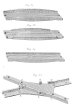 |
Fig. 4 [207.2kb] |
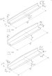 |
Fig. 5C [207.2kb] |
Farey's description in general supports that given by others, but with dimensional differences, the most significant heing the length of 3 feet 2 inches, which in all other accounts and on actual specimens of both Surrey Iron Railway and Croydon, Merstham and Godstone Iron Railway rails is 3 feet. The "small circular projection" is not present in any other descriptions or drawings, but does exist, in a different form, on the extant Croydon, Merstham and Godstone Iron Railway rails.
Von Oeynhausen and Von Dechen wrote in 1827 that "The first rails employed were 4 in. wide on the flat and nearly 1 in. thick, with a flange 3 in. high and ½in. thick. These have become much damaged by the use of narrow wheel treads, as deep grooves are made. At present, therefore, the rails are used with a strengthening rib underneath, which is highest in the middle and tapers to nothing at the ends, so also are the upper flanges made higher in the middle than at the ends, to give more strength to the rails." [6] A writer in 1841 also stated that the problem caused by the weak form of the original rails "has been to some degree remedied by the use of a rail with an under rib .... a form which was adopted to reduce the cost of repairs on the Surrey tramroad." [7] These two references support Tredgold's account of the original rails being replaced, as and when they were damaged, by a stronger pattern incorporating an under rib, and similar to the Croydon, Merstham and Godstone Iron Railway rails.
As regards the Oroydon, Merstham and Godstone Iron Railway rails, it is possible to be more definite, as a number of rails marked with the initials of the company have been found at various times in the vicinity of the Merstham terminus. Bruce Osborne has made a study of these, together with similar rails found in the Godstone Hills stone mines, and the following particulars are for the most part extracted from his, report, published in 1982. [8]
The Croydon, Merstham and Godstone Iron Railway rails are 3 feet long, with a vertical curved flange 3 inches high at the centre and 2 inches at the ends, above a horizontal running plate which is of 4 inches clear width. There is a strengthening rib on the underside of this, 1 inch deep at the centre from the surface of the running plate, tapering to nothing at the ends. On the outside face of the flange, at each end, is a small curved "buttress". (Fig.5 (C))
On the top of the horizontal plate is embossed in one inch high letters at one end, "Ry C" a.nd at the other end, "CM&.G" SO that across the joint of two adjacent rails they read, "CM&GRyC". On the underside is embossed the words "OUTRAM & CO" or "OUTRAM". '
Of the 27 rails examined by Osborne, all except one were found at various times at the former Merstham Lime-works. They include rails found in situ in 1967, and during excavations carried out in 1971-72 by the Surrey Archaeological Society, and also 13 forming a display at Merstham, which were subsequently stolen, early in 1982. A 14th. had disappeared some years earlier. These 14 had probably been part of a collection assembled by J.S.Peters, the manager of the limeworks, in his garden at Quarrydene in the 1930s, set up on stone sleepers also found in the area.
These 27 examples included three rails of a variant pattern, being heavier and having only the letters "C.MG"; and also a single rail embossed "CMG" and "RC" which had an additional rib in the middle of the underside.
A number of rails found in the Godstone Hills quarries, similar to the standard Croydon, Merstham and Godstone Iron Railway type, bear the words "OUTRAM" or "OUTRAM CO", but not the railway initials. Osborne concluded that these rails had been supplied by Outram and Company independently at about the same time that the railway was built, or even earlier; and that the widely-held assumption that they were ex-railway rails, possibly obtained after the railway had closed, was questionable. The same conclusion had been reached by K.W.Bean in 1970, based on his examination of rails found in the Godstone mines. [9] This conclusion must, however, be modified by the later discoveries of Peter Burgess, who found, after cleaning, that a number of the rails found at Godstone, and others in situ there, were in fact marked with the railway company's initials. [10]
The gauge of the railways, for long a matter of speculation, was finally settled in February,1967, when W.G.Tharby and others excavated a short section of track in situ near the former Quarry Dean Farm at Merstham. The distance between the centres of the spikes was found to be 4 feet 6 inches, and between the inside faces of the fla,nges was 4 feet 2 inches, which represents the gauge, and corresponds with Outrams "best width of road for general purposes." [11]
There was no standard pattern for the wagons used on the railways, . but principles and features evolved in the design of road wagons, led to a common basic design adapted and modified to suit rail transit. The manufacturers and carriers would have used models specifically built to suit the loads and materials to be carried.
A general description of the wagons in use was given in Farey's article in Rees' Cyclopaedia: "The wagons in most general use on the Surrey Iron Railway weigh, including their lading, about 3¼ tons, the wheels are two feet five inches high, of cast iron, with 12 spokes, which get wider as they approach the hub, which is eight inches long to receive a small wrought iron axle: the fellies or rims of the wheels are two inches broad, and nearly as much thick, and the sharp angles are rounded off, so that these wheels are capable of being used without damage on any hard common road; a very principal advantage attending the modern use of rail-ways. The axles of the wheels are fixed at two feet seven inches distance: the bodies of these wagons are seven feet nine inches long, four feet five inches wide, two feet four inches high; these are used for bringing down chalk from the Surrey hills to make lime, carrying back manure &c. The founders and others upon the line, have trucks or wagons of different kinds to suit the nature of their goods: the only apparent limitations being in the width of the wheels and carriage, the length of their axles, and the weight of lading." [5]
W.B.Paley pointed out that the dimensions given meant that the front and rear wheels only just cleared each other, and that a longer wheel base would have prevented two wheels being on a rail at the same time, thus reducing the incidence of breakage of the rails. [12]
Despite the reference to the wagons being suitable for use on common roads, there is no evidence that this was the practice, and other contemporary accounts indicate that they were not so used.
Tredgold in 1825 gave differing dimensions: "The waggons weigh about a ton, and are 5 feet wide, 8 feet long and 2 feet deep; they are allowed to carry 3 tons, and not exceeding 3¼ tons. The wheels are of cast iron, 1½ inches in breadth at the rim, and 32 inches diameter; they revolve on conical axles, 2? inches diameter at the shoulder, and 1½ inches at the linchpin." [4]
James Malcolm referred to a special design of wagon: "Some of the waggons are made to shoot their loads, the front wheels are then placed quite forward, and the other two exactly under the centre of the body of the carriage, each 'wheel is two feet high, and the length of the waggon about 6 feet." [13]
 |
Plate 4 [207.2kb] |
W.Thurston Hopkins wrote in 1930 that a number of Surrey Iron Railway wagon wheels had been set up to form a breakwater in the River Wandle near Crown Mill at Mitcham. [14] The breakwater has long since gone but in 1963 a broken wheel was found in the bank on the site, and in October,1969, a complete wheel was found in the river bed nearby. The incomplete wheel is now on display at the Wandle Industrial Museum, and the complete wheel is kept at the Guildford Museum-, The latter is 2 feet 8 inches in diameter, with a 1½ inch wide rim, and having 9 spokes. [15]
The Hull Railway Museum possessed an artist's impression of wagons used on the Surrey Iron Railway (Plate 4), and a full-sized reconstruction of such a wagon, which was destroyed by bombing in World War II. A small model of a wagon, constructed by John Williams and based on a painting of the Croydon, Merstham and Godstone Iron Railway by G.B.Wollaston dated 1823, is on display at the East Surrey Museum, Caterham.
|
|
|
|